AC Power Theory - Advanced Maths
This page covers the mathematics behind calculating real power, apparent power, power factor, RMS voltage and RMS current from instantaneous Voltage and Current measurements of single phase AC electricity. Discrete time equations are detailed since the calculations are carried out in the Arduino in the digital domain.
For a much nicer Arduino code snippet version of this page, see: AC Power theory - Arduino maths.
Real Power
Real power (also known as active power) is defined as the power used by a device to produce useful work.
Mathematically it is the definite integral of voltage, u(t), times current, i(t), as follows:

Equation 1. Real Power Definition.
U - Root-Mean-Square (RMS) voltage.
I - Root-Mean-Square (RMS) current.
cos(φ) - Power factor.
The discrete time equivalent is:

Equation 2. Real Power Definition in Discrete Time.
u(n) - sampled instance of u(t)
i(n) - sampled instance of i(t)
N - number of samples.
Real power is calculated simply as the average of N voltage-current products. It can be shown that this method is valid for both sinusoidal and distorted waveforms.
RMS Voltage and Current Measurement
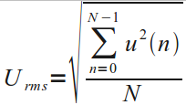
An RMS value is defined as the square root of the mean value of the squares of the instantaneous values of a periodically varying quantity, averaged over one complete cycle. The discrete time equation for calculating voltage RMS is as follows:

Equation 3. Voltage RMS Calculation in Discrete Time Domain.
RMS current is calculated using the same equation, substituting voltage samples, u(n), for current samples, i(n).
Apparent Power and Power Factor
Apparent power is calculated, as follows:
Apparent power = RMS Voltage x RMS current
and the power factor is calculated from the definition:
Power Factor = Real Power / Apparent Power
Harmonics, Non-Linear Loads and Power Factor
A non-linear load, such as a fluorescent light, a computer power supply or a variable speed drive in a washing machine, will distort the mains current wave and generate harmonics of the fundamental mains frequency, and a side effect is the voltage wave will also be distorted. This leads to power existing not only at the mains frequency, but at harmonics of that frequency too. This has implications for the accuracy of power measurements. References where this is covered are given below.
Adding RMS Values
The combined r.m.s. value of a signal with harmonic components is the square root of the sum of the squares of each component:

The d.c. bias voltage added to the input to the analogue to digital converter can be removed if we recognise that the d.c. value can be represented by RMS1, the wanted input less the bias offset by RMS2, and the value we have from the ADC is RMSTotal. Or:

That is the method used in emonLibCM in the rearranged form:

This method is much faster than applying a digital filter to each individual sample, and it is valid because it is reasonable to assume that the offset – the average value of all the samples – will remain sensibly constant for the duration of the sampling period.
References
Pages 12-15 of Atmel’s application note for the ‘AVR465: Single-Phase Power/Energy Meter with Tamper Detection’:
http://ww1.microchip.com/downloads/en/Appnotes/Atmel-2566-Single-Phase-Power-Energy-Meter-with-Tamper-Detection_Ap-Notes_AVR465.pdf
‘How Harmonics Have Contributed to Many Power Factor Misconceptions’, Anthony (Tony) Hoevenaars, P. Eng, Mirus International Inc.:
https://www.mirusinternational.com/downloads/MIRUS-TP003-A-How%20Harmonics%20have%20Contributed%20to%20Many%20Power%20Factor%20Misconceptions.pdf
How Harmonics Have Contributed to Many Power Factor Misconceptions (PDF)
A Wikipedia page:
https://en.wikipedia.org/wiki/Power_factor