How to take component tolerances into account
When designing any circuit, it is necessary to take account of the unavoidable variations that arise as part of the manufacturing process which lead to the value of some characteristic of the component - the resistance of a resistor or the voltage of a regulator - differing from the desired value.

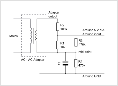
Arduino AC voltage input circuit diagram
To enable the best use of the Arduino analog input range, the input voltage should swing between 0 V and the supply voltage, nominally +5 V. To do that successfully, we must take the worst case conditions into account when we do the calculation.
The AC mains voltage isn’t always 240 V (or whatever it should be in your locality). Normally, the voltage will vary by up to 10% either side of the nominal value. For safety, we must use the highest possible voltage for the calculations.
The adapter is not working at full load. If the unloaded voltage of the adapter is known, use that. Otherwise, for the type of adapter normally used, add 20% to the nominal voltage.
The Arduino voltage supply may not be exactly 5 V. The voltage regulator output may lie between 4.8 V and 5.2 V. The worst case is when the voltage is low, so we must use 4.8 V in the calculations.
The bias chain resistors might not be equal. Each resistor may be wrong by 1%, the worst case is if they are wrong in opposite directions, when the midpoint will be 1% wrong.
The divider chain resistors might be wrong. Each resistor may be wrong by 1%, the worst case is if R2 is low and R1 is high. In this case because they are significantly different values, the divided voltage will be 2% high.
How does this work in practice? Let us assume we have a Mascot adapter and we are in the UK. The highest UK mains voltage is 240 V + 6%, or 254.4 V. The adapter is labelled “Input: 230 V, Output 9 V”, so the output voltage might be as high as 9 × 254.4 / 230 = 9.95 V, to which we must add 20% because there is no load, so 11.95 V. This is the rms value, the peak value is 11.95 V × √2 = 16.9 V.
The voltage we want at the Arduino input is 4.8 V peak-to-peak, but the entire range is available only if the bias is exactly at the midpoint of 2.4 V. The midpoint may be as low as 2.376 or as high as 2.424 V (it doesn’t matter which), so our peak AC voltage is restricted to 2.376 V.
Let’s choose an R1 value of 10 kΩ, except of course, it isn’t, it is high by 1%, so the actual value is 10.1 kΩ. That means the peak current in R1 is 2.376 V ÷ 10.1 kΩ = 0.235 mA. This current also flows in R2 and the voltage across R2 is 16.9 V - 2.376 V, so the exact value for R2 is (16.9 - 2.376) V ÷ 0.235 mA = 61.8 kΩ. Under our worst-case conditions, this is 1% low, so the ideal resistor should be 62.42 kΩ. Unfortunately, this is a little above a standard value. If it is acceptable to risk clipping the waveform under very worst case conditions, a 62 kΩ resistor could be used. Otherwise the next higher, standard value, 68 kΩ, must be chosen.