EmonPi Install Guide
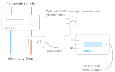
The following guide provides an quick overview of how to setup the hardware part of an emonPi energy monitoring system for monitoring up to two AC circuits.

Warning
Please read the CT installation guide before installing. Your safety is your responsibility. Clip-on current sensors are non-invasive and should not have direct contact with the AC mains. However, installing the sensors will require working in close proximity to cables carrying high voltage. As a precaution, we recommend ensuring the cables are fully isolated; i.e., switch off the power prior to installing your sensors and proceed slowly with care. If you have any doubts, seek professional assistance.
1. CT sensor
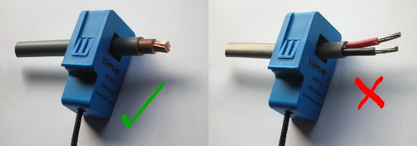
Clip the CT sensor around either the Line or Neutral cable
Connect jack plug into either CT1 or CT2 socket on the emonPi
If the power reading is negative, reverse the CT sensor orientation
CT sensor cable should not be extended to avoid induced noise
For Solar PV install see Solar PV Application page
Note
The clip-on CT sensors must be clipped round either the Line or Neutral AC wire. NOT BOTH
2. AC-AC Adapter
Plug the AC-AC adapter into a power outlet
This may require installation of a new outlet or extending an existing one
AC-AC adapter cable can be extended if required
Plug power connector into the AC socket on the emonPi
Essential for Solar PV monitoring
Provides AC waveform reference for accurate Real Power measurements.
Learn more about measuring voltage with AC-AC power adapator…
3. DC 5V USB Adapter
Plug the DC 5V USB adapter into a power outlet
Plug the mini-B USB connector into the emonPi
High quality minimum 1.2A power supply recommended
4. Optical Utility Meter LED Pulse Sensor (optional)
Connects to emonPi / emonTx via RJ45 connector
Self-adhesive velcro attachment to utility meter
One optical pulse sensor per emonPi/emonTx
Can be used in conjunction with temperature sensors using RJ45 Breakout
5. Temperature Sensors (optional)
Connect to emonPi / emonTx via RJ45 connector.
Up to 6x RJ45 sensors can be connected using the RJ45 expander.
Up to 6x wired sensors can be connected using the terminal block breakout board.
Sensor wire can be extended using RJ45 cable and the RJ45 Extender.
6. Installation Examples
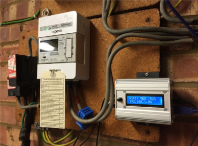
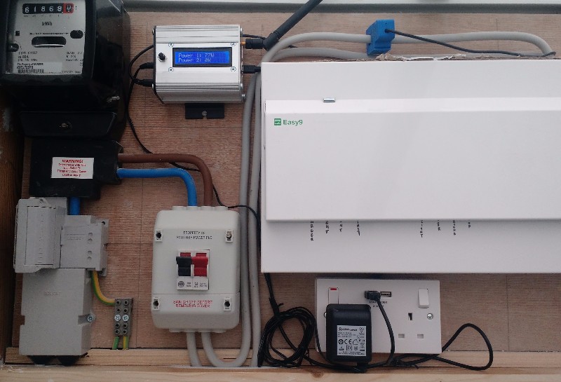
The included clips can be used to mount the emonPi / emonTx on a wall.
See Solar PV Application Note for emonPi solar PV install guide & images.
7. Power Up
Note
Ensure all sensors are connected before powering up.
a.) Switch on DC & AC power
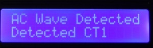
b.) Check CT sensor(s) & AC Wave are detected:
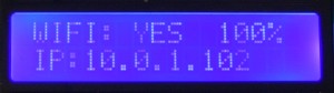
c.) emonPi should remember WiFi network and re-connect
8. Shutdown
Optional: Shut down the emonPi, hold down the shutdown button for 5 seconds, then wait 30 seconds for unit to fully shut down.

Warning
Unplugging power from the emonPi without following the correct shutdown procedure can result in a corrupted SD card.