Other sensors
Temperature sensing
The emonPi2 supports temperature sensing via DS18B20 temperature sensors. These are small temperature sensors with a 12-bit ADC and a digital output all in the sensor itself. Communication is over a one-wire bus and requires little in the way of additional components. The sensors have a quoted accuracy of ±0.5°C in the range -10°C to +85°C.
Tip
Temperature sensing is handled by the RaspberryPi directly rather than the measurement board microcontroller. This removes the hard limit on the number of temperature sensors that can be connected to the bus and allows sensor addresses to appear directly on the Emoncms inputs page. It also improves the accuracy of the electricity monitoring as the measurement board is freed up to focus soley on this task.
We have tested up to 6 temperature sensors connected at once, the one-wire bus should however support more than this. There is a useful discussion on how many sensors can be supported on a single RaspberryPi GPIO input here.
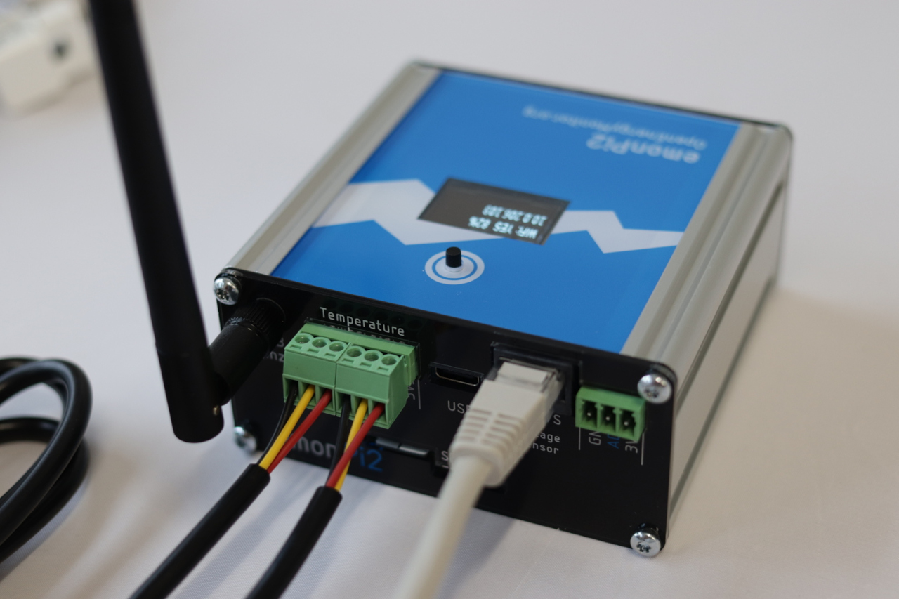
DS18B20 temperature sensors are connected via the labelled pluggable terminal blocks (multiple sensors can be connected to each temperature input, e.g using a 6x sensor breakout board). Please note that temperature sensing is not broken out on the RJ45 connector which is for voltage sensing and power only.
Pluggable terminal block connections are:
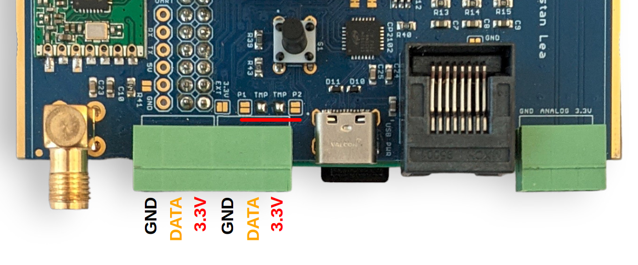
GND (black), DATA (yellow), 3.3V (red), left to right, repeated for each of the three blocks:
The function of the emonPi2 terminal blocks can be changed with small solder-jumpers just above the terminals on the measurement board PCB. The default configuration is 2x temperature sensor inputs, one on each terminal block. Notice the bridged solder jumpers labelled ‘TMP’ in the picture below:
The DS18B20 input is connected to GPIO17 on the RaspberryPi via the GPIO connection header. *It is also connected to digital PIN_PB4 on the AVR128DB48 microcontroller for use in transmitter mode as part of an emonTx5.
Pulse counting
Update 14th May 2024: When running the latest emonPi2 single phase or three phase firmware, pulse counting is attached to the analog input as standard which leaves the other terminals for easier connection of multiple temperature sensors.
The OpenEnergyMonitor pulse counter can connected like this:
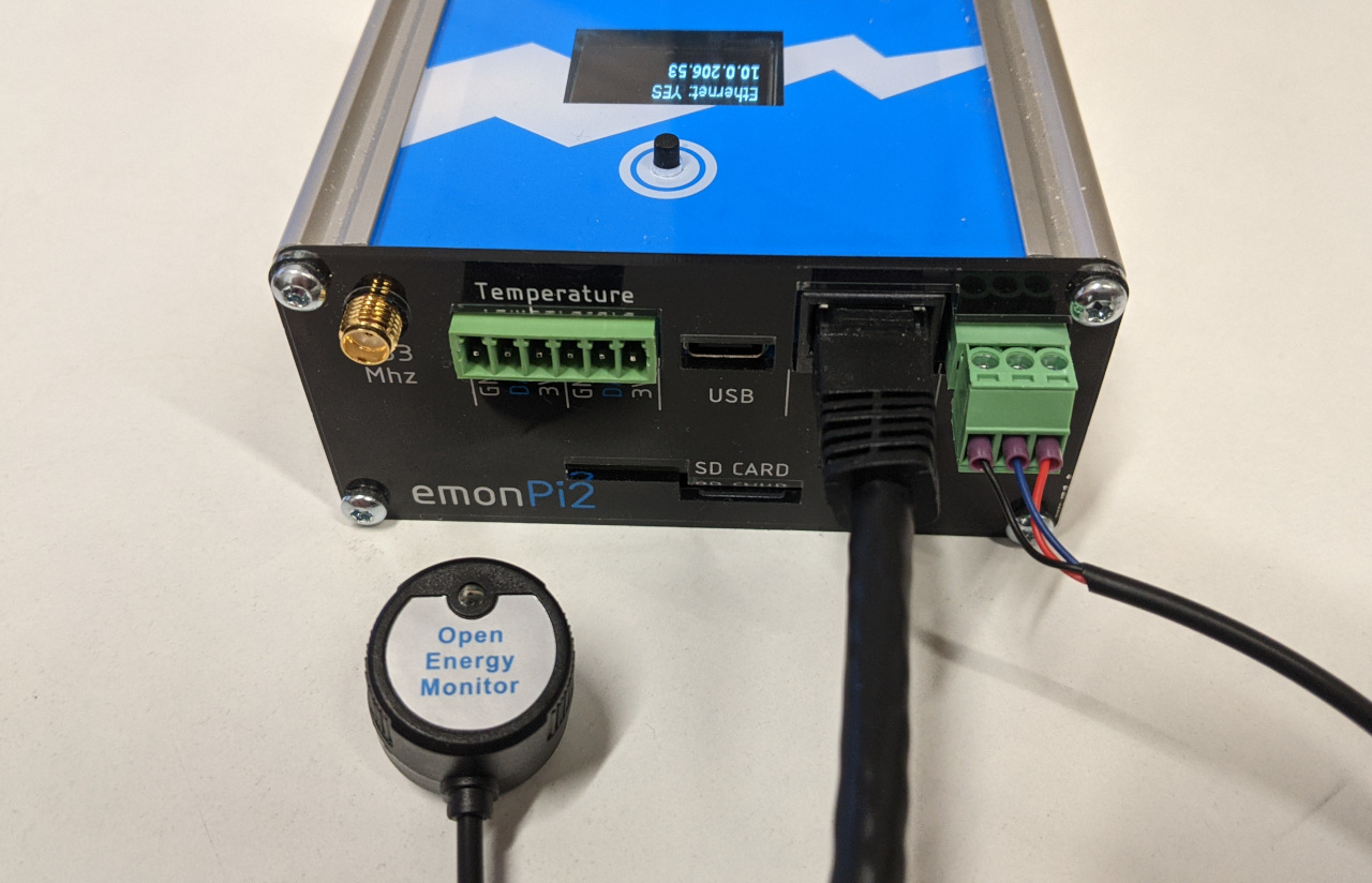
This pulse input will appear alongside the energy monitoring data from the emonPi2 on the emoncms inputs page. Note that the voltage sensor is required for this firmware to work.
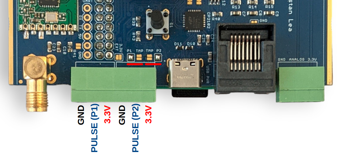
Pulse sensing using the terminals labelled ‘temperature’:
While the left hand side terminal block inputs are configured for temperature sensing as standard, it’s possible to change the function of the ‘Data’ pin on each of the terminal block inputs. The following picture shows both inputs configured for pulse counting rather than temperature sensing, notice the moved solder pad bridges:
Note
T1 can be either a pulse input (Pi GPIO27 PIN13 or AVR-DB PIN_PB5) or temperature sensing (Pi GPIO17 or AVR-DB PIN_PB4)
T2 can be either a pulse input (Pi GPIO22 pin-15 or AVR-DB PIN_PC0) or temperature sensing (Pi GPIO17 or AVR-DB PIN_PB4)
It is easy to increase the number of pulse inputs when temperature sensing is not required. Simply select the P1 and P2 solder bridges above and add the following emonhub.conf interfacer configuration. This will enable direct readings from the applicable pulse inputs on the Pi, bypassing the AVR-DB microcontroller:
[[pulse1]]
    Type = EmonHubPulseCounterInterfacer
    [[[init_settings]]]
        pulse_pin = 13
        # bouncetime = 2
        # rate_limit = 2
    [[[runtimesettings]]]
        pubchannels = ToEmonCMS,
        nodeoffset = 1

[[pulse2]]
    Type = EmonHubPulseCounterInterfacer
    [[[init_settings]]]
        pulse_pin = 15
        # bouncetime = 2
        # rate_limit = 2
    [[[runtimesettings]]]
        pubchannels = ToEmonCMS,
        nodeoffset = 2
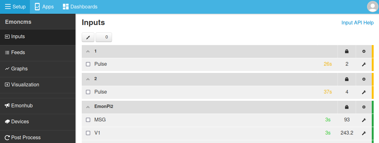
On pulse detection, the pulse inputs will appear on the Emoncms inputs page:
Analog input
It’s possible to link analog input AIN19 (CT12) to right-most terminal block as shown here. An example application is measuring flow rate using a Sika VFS which has an analog voltage output.
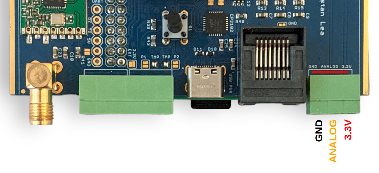
Warning
The analog input voltage must be in the range 0 - 1.024V. This ADC is configured for this range in order to suit the 333mV CT sensors. This analog input can not be used when using the emonPi2 with the C.T Extender board.
Using the analog input requires compiling and uploading custom configuration of the emonPi2 firmware. Start by setting up the Arduino IDE environment following the firmware guide.
Open the base firmware emon_DB_6CT from the avrdb_firmware firmware repository.
1. Make sure to select EMONPI2 as the hardware variant:
// 1. Set hardware variant
// Options: EMONTX4, EMONTX5, EMONPI2
#define EMONPI2
2. Uncomment the line #define ENABLE_ANALOG:
// 6. Enable analog reading (disabled by default)
// #define ENABLE_ANALOG
3. Select 1phase or 3phase as required:
// 3. Set number of voltage channels (1 for single phase, 3 for three phase)
#define NUM_V_CHANNELS 1
4. Compile and upload the firmware to the emonPi2
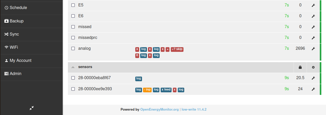
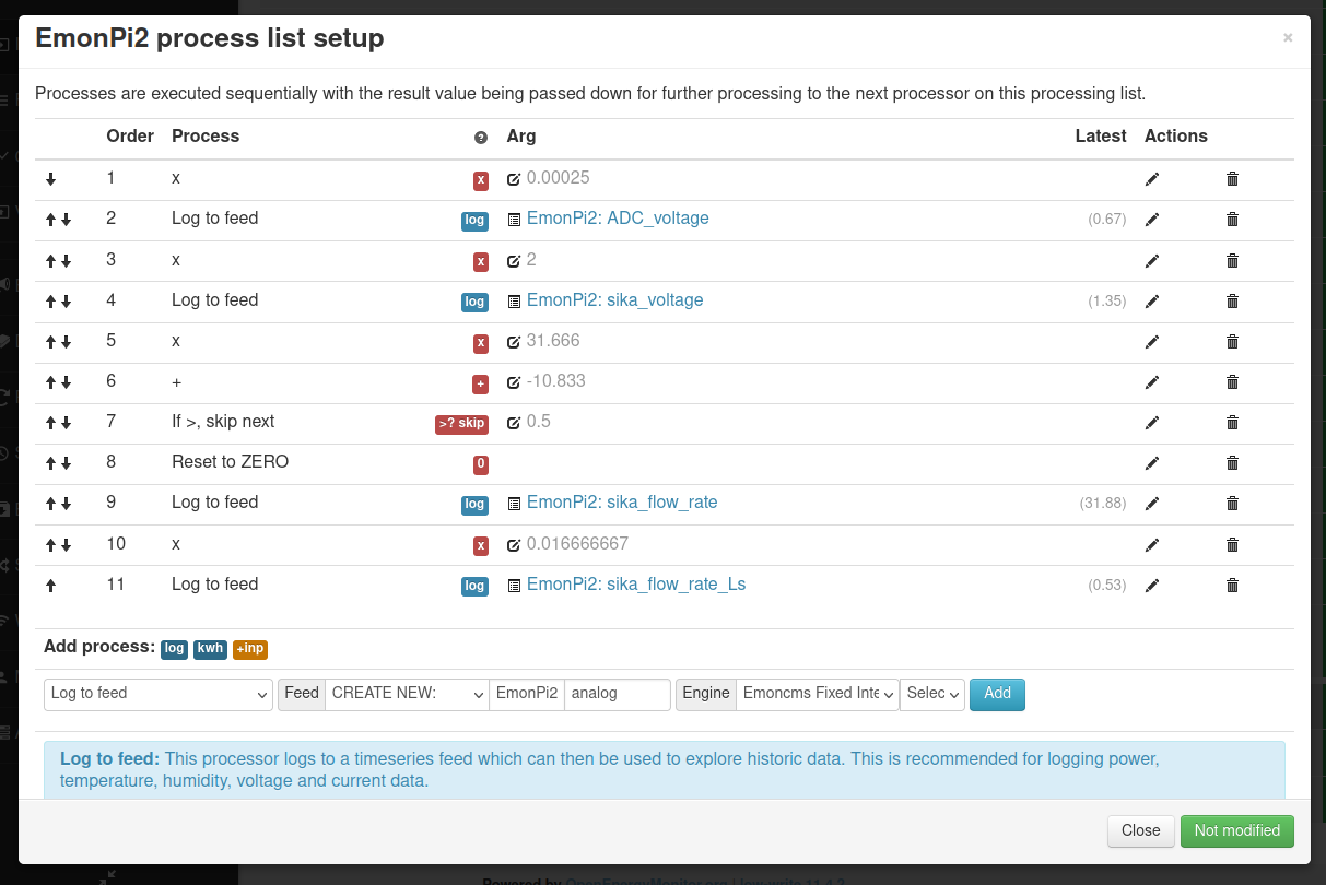
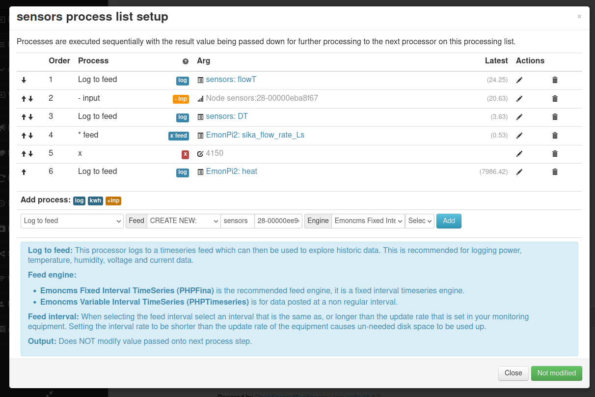
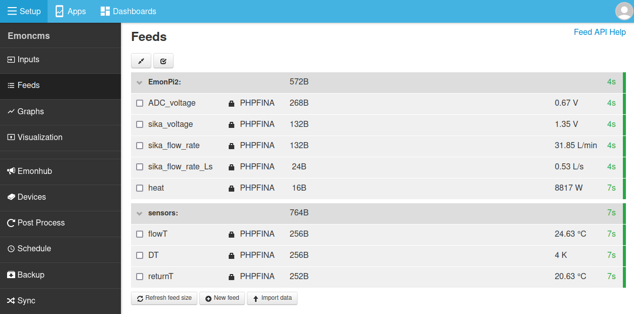
With this firmware loaded the analog input will appear in the input list.
The following set of screenshots gives an example of configuring this analog input for use in reading the flow rate from a Sika VFS flow sensor. The flow rate is then used together with measurement of flow and return temperature to calculate heat.