Extending the Current Transformer Cable – emonPi2 & emonTx4 Onwards
Note: This advice does not apply to the earlier emonPi and emonTx V2 & V3.
In some installations, it might be necessary to extend the cable from a current transformer (c.t.). Often, this is because you want to measure real power, but there is no power socket at, or close to, the only place where you can mount the c.t. If this is the case, your only option may be to extend the c.t. cable.
The output from the current transformer used with the ‘emon’ devices is a low voltage at mains frequency, which will range from zero to 333 mV rms. There should be no real limit to the maximum length of the cable that you can have. Voltage drop is largely irrelevant because of the relatively high input impedance of the emonTx or emonPi, and the main limiting factor is likely to be interference from outside sources.
Materials
A length of twin screened “microphone” cable. Shielded (i.e. screened) Ethernet cable can be used.
A 3-pole “stereo” 3.5 mm jack plug.
A length of wire to earth the cable screen.
Sleeving to insulate & protect the joints.
Choice of cable
You should choose a cable designed for microphones. This will have twin twisted cores with an overall braided screen. A ‘braided’ screen is better than ‘lapped’. The more tightly the screen is woven, the better it will be at keeping out interference.
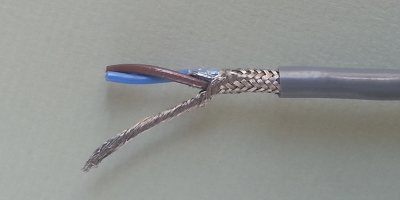
This is a high quality cable of the kind that is suitable.
The current rating of the conductors will be irrelevant, and you should choose a cable that is strong so that it will safely resist any possible mechanical damage. The cable cores (but not the cable screen and sheath) should be small enough to pass through the entry opening in the 3.5 mm plug housing.
Wiring
Remove the 3.5 mm jack plug from your c.t. (If it is moulded on, you must cut it off. If you do not wish to cut the plug off, obtain an “in-line” socket.)
Install the cable and prepare the ends.
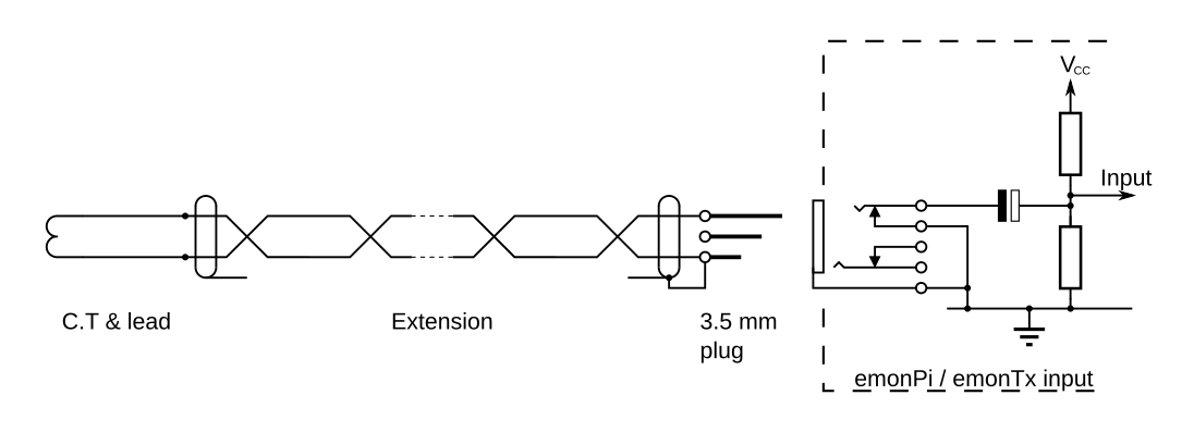
At both ends, strip back the outer sheath. At the emonTx/emonPi end where you will make the earth connection, comb out (or unwind) the cable screen. Join the earth wire to the screen, and connect to the earth connection. You can use either the sleeve connection of the jack plug, or one of the GND connections on the green 3-pin plugs. Connect the two cores of the extension cable to the plug tip and sleeve. There is no connection to the plug ring.
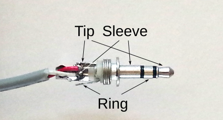
At the c.t. end, cut back and insulate the cable screen. Join the two cores of the c.t’s cable onto the two inner cores of the new cable. To maintain the phase relationship, ensure that the core of the c.t’s cable that went to the plug tip still connects via the extension cable to the plug tip, and the other core that connected to the plug sleeve still connects via the extension cable to the plug sleeve. If you have an American c.t. with white and black twisted wires, connect the white wire through the extension cable to the plug tip and the black wire to the sleeve. Do not connect the screen of the c.t’s cable (if it is screened).
Can I use a ready-made headphone extension lead?
If it is screened, then it will probably be OK. If it is unscreened, then it may be OK, but this is not ideal. It will be liable to pick up interference from adjacent wiring etc.
Can I use network cable?
If you have a screened cable (FTP/STP or S/UTP, CAT5 or CAT6), then this should be OK, and can be an attractive solution if you have several c.t’s at the same location. An unscreened cable is not ideal, and will be more liable to pick up unwanted interference from adjacent wiring etc. Bear in mind that the cores of the network cable might not be stranded, which would make them liable to break more easily than a stranded conductor.
I have several C.T’s in one place. Can I use a multi-core cable?
Yes, but ideally you want a telephony-type cable where pairs of wires are twisted together. Use one pair for each c.t.
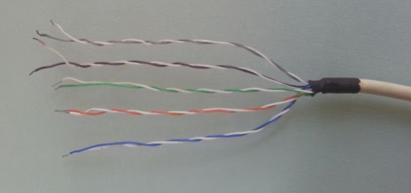
If you must use a multicore cable that does not have twisted pairs, try to pick the pairs of wires at random, so that all the ‘signal’ wires and all the ‘earthy’ wires are not bunched together.
You should try not to use one common connection for one side of all the c.t’s. If it is impossible to avoid a common connection, you must connect the common connection to the ‘earthy’ side of the jack plug at the emonTx or emonPi, which is the plug sleeve. (Check the circuit diagram for any other device.)
What if I see a significant power when there should be none?
You probably have noise (interference) picked up because the extension is acting as an aerial. Take a careful look at the cable route. Does it run close to another mains cable? If it is, is it possible to route it some distance away? The further you can, the better.
If that doesn’t help, then if possible try earthing the other end instead.
Also, try earthing the case of the emonTx or emonPi. Check first, the metal case is normally isolated, with no connection to either the d.c. power input or the a.c. voltage sampling input. If there is a connection between the case and any part of the circuity inside (and the easy way to check is to test for continuity between one of the screw heads and the antenna socket body) then there is a possible risk of damage and you should not earth the case. Earthing the case has in one installation significantly reduced the falsely indicated power.
Theory
There are two routes by which interference can get into the cable, and so be measured along with the wanted signal – as a magnetic field or as an electric field.
The magnetic field is counteracted by twisting the cores inside the cable. Alternate half-twists will pick up the field in the opposite sense, so the induced currents will cancel. The cable screen will have little or no effect.
The electric field will be intercepted by the cable screen, and conducted to earth through the earth connection. It is important not to earth the screen at both ends, as this could give rise to a current that circulates in the loop formed by the cable screen, earth and the two earth connections.