EmonTH v2 Install
Data from the emonTH is transmitted via wireless RF (433MHz) to an emonPi / emonBase web-connected base-station for logging to Emoncms for data logging, processing and graphing.
With the 2x AA batteries installed and the emonTH powered up. The emonTH is designed to appear automatically in the emoncms input list on the emonPi/base. For systems with only one emonTH no further hardware setup is required.
If more than one emonTH is to be used with the same base-station, each emonTH will need a different RF node ID.

Standard setup
1. Power Up
Power emonTH from 2 x AA batteries
Alternatively 5V DC can be wired into terminal block if required
2. Indicator LED
Illuminates solid (dimly) for a few seconds at first power up
LED should then extinguish to indicate successful sensor detection
Flashing LED indicates sensor detection failure
To preserve battery LED does NOT flash regularly during operation
3. Emoncms Setup
RF transmission from the emonTH will be picked up automatically and data will appear in local Emoncms Inputs page.
If Remote logging has been setup, data will also be posted to Emoncms.org.
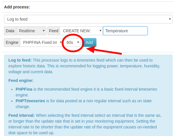
See guide Log Locally for an overview of logging inputs to feeds. For EmonTH inputs select a feed interval 60s or greater:
Note
Important: the emonTH reports data at a 60s interval, it’s important to log the data to emoncms with a 60s inerval as shown below.
Note
If using more than 4x emonTH units (with custom RF node ID or modified firmware) emonhub.conf node decoders will need to be setup.
Changing the emonTH node ID
DIP Switch Config
The on-board DIP switch can be used to select up to four node IDs:
DIP 1 |
DIP 2 |
RF node ID V1.x firmware |
RF node ID V2.x firmware |
|---|---|---|---|
OFF |
OFF |
19 (default) |
23 (default) |
ON |
OFF |
20 |
24 |
OFF |
ON |
21 |
25 |
ON |
ON |
22 |
26 |
Serial Config
The emonTH node ID can also be changed using a USB to UART cable and the Arduino IDE.
Add: External temperature sensor/s
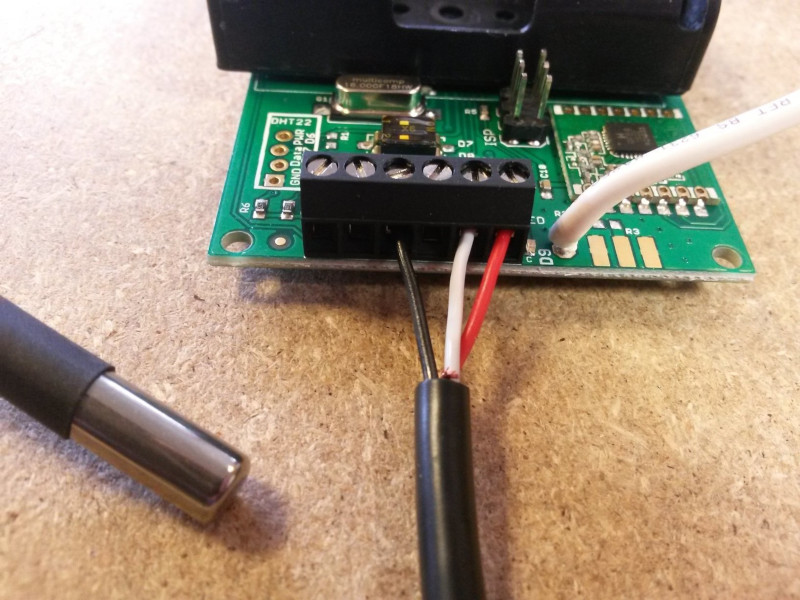
The standard emonTH2 firmware supports connecting one external DS18B20 temperature sensor.
Black: GND
Red: Power (digital I/O 5 is used as the power pin to enable sensor power-down between readings to save power)
White: ADC5 (Dig 18) one-wire bus
Multiple temperature sensors
The master branch supports multiple external DS18B20 sensors. It is configured to only read and publish the output of the first sensor by default.
In order to add more sensors, you need to do four separate things.
Connect the additional sensors on the terminals
Modify the source files
Check out the repository and open
emonth2.ino.Then Increase the value of
EXTERNAL_TEMP_SENSORSto match the number of connected sensors here [https://github.com/openenergymonitor/emonth2/blob/master/firmware/emonth2.ino#L134]Upload the firmware with
pio run -t upload
Update the sensor configuration in EMonHub to match your number of external sensors. For example, for two external sensors change it like this, by adding an additional external temperature under
names,datacodesandscales:
    [[25]]
        nodename = emonth2_25
        [[[rx]]]
            names = temperature, external temperature 1, external temperature 2, humidity, battery, pulsecount
            datacodes = h, h, h, h, h, L
            scales = 0.1, 0.1, 0.1, 0.1, 0.1, 1.0
            units = C, C, %, V, p
You may need to change the setting for enabling/disabling the external probes on the serial console by hitting
+++andenterafter a reset and enteringt0 1after the prompt
Add: External optical pulse sensor
The EmonTH has a digital input (with interrupt) that can be used for pulse counting. This can be used for wired pulse counting or with the Optical LED pulse sensor.
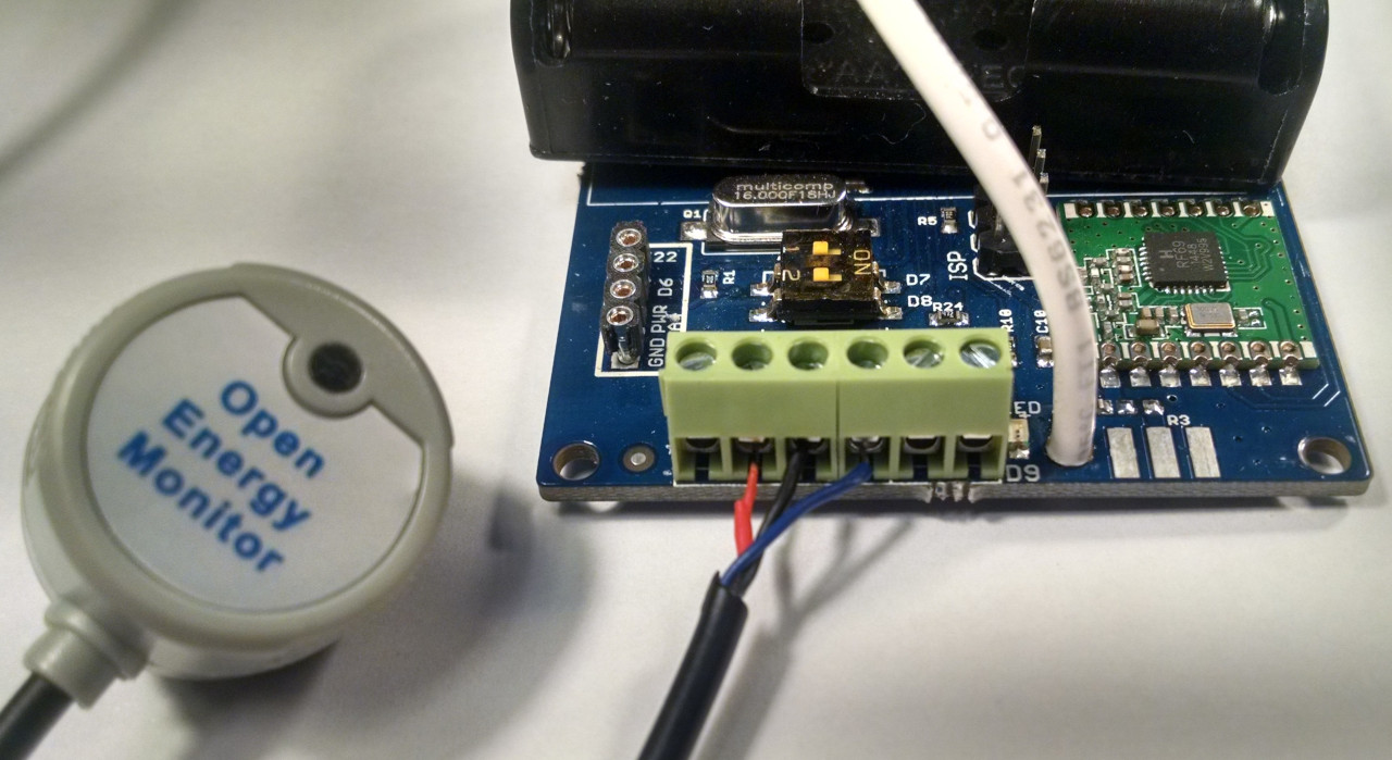
To use the Optical LED Pulse sensor the easiest way is to remove the RJ45 connector and then strip back the black sheathing to reveal the red (3.3V power), black (GND) and blue (pulse) wires.
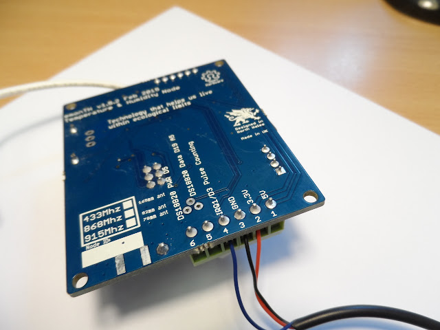
Connect the red wire to the 3.3V terminal, the black wire to the GND terminal and the blue wire to the terminal labelled D3 (top) or IRQ1/D3 Pulse Counting (bottom of the board).
Red: 3.3V
Black: GND
Blue: IRQ1/D3
Input pull-up
There is an input pull-up inside the pulse (IRQ) input that is enabled in the standard sketch. Therefore, you can connect a volt-free contact or an SO output between screw terminal 4 (IRQ input, SO+) and screw terminal 3 (GND, SO-) without the need for an additional resistor. If you must connect your contacts between VCC (screw terminal 2) and screw terminal 4, then you must add a pull-down resistor of resistance low enough to overcome the internal pull-up resistor, or you can use a higher-value resistor and modify the sketch to disable the internal pull-up.
If you are using a reed switch, you may find that you get more than one count per pulse. Adding a 0.1 µF capacitor across the reed switch has been shown to eliminate this problem.
Emoncms input processing
To record the total accumulated pulse count in emoncms use the wh_accumulator input process which detects resets continuing the total pulse count accumulation from the last value before the reset.