Configuration
DIP Switch
The on board DIP switch can be used as a convenient way to change both the node ID and the voltage calibration of the emonTx3.
Multiple emonTx unit’s can operate on a single network posting to a single emonBase web-connected base station, each emonTx on the same network group must have an unique node ID. If more than two emonTx’s are required on the same network then further nodeID values can be set via RF node ID serial config.
The following image shows the DIP switch configuration looking at the emonTx with the CT sensor inputs at the top of the board.
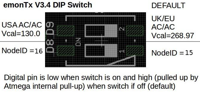
Move the top switch D9 to the left to select USA ACAC Voltage calibration.
Move the bottom switch D8 to the left to select RF node ID 16 rather than 15.
Serial Configuration
It’s possible to set the emonTx3 radio settings, sensor calibration and other properties over serial using the arduino serial monitor or other similar tool.
The following details the available commands and their function:
l list the settings
r restore sketch defaults
s save settings to EEPROM
v show firmware version
z zero energy values
x exit, lock and continue
? show this text again
w<x> turn RFM Wireless data off: x = 0 or on: x = 1
b<n> set r.f. band n = a single numeral: 4 = 433MHz, 8 = 868MHz, 9 = 915MHz (may require hardware change)
p<nn> set the r.f. power. nn - an integer 0 - 31 representing -18 dBm to +13 dBm. Default: 25 (+7 dBm)
g<nnn> set Network Group nnn - an integer (OEM default = 210)
n<nn> set node ID n= an integer (standard node ids are 1..60)
d<xx.x> a floating point number for the datalogging period
c<n> n = 0 for OFF, n = 1 for ON, enable current & power factor values to serial output for calibration.
f<xx> the line frequency in Hz: normally either 50 or 60
k<x> <yy.y> <zz.z>
Calibrate an analogue input channel:
x = a single numeral: 0 = voltage calibration, 1 = ct1 calibration, 2 = ct2 calibration, etc
yy.y = a floating point number for the voltage/current calibration constant
zz.z = a floating point number for the phase calibration for this c.t. (z is not needed, or ignored if supplied, when x = 0)
e.g. k0 256.8
k1 90.9 2.00
a<xx.x> a floating point number for the assumed voltage if no a.c. is detected
m<x> <yy> meter pulse counting:
x = 0 for OFF, x = 1 for ON
yy = an integer for the pulse minimum period in ms. (y is not needed, or ignored when x = 0)
t<x> turn temperature measurement on or off: x = 0 for OFF, x = 1 for ON
Note
If a custom node ID is set, a corresponding node decoder needs to be in place in emonhub.conf to decode the EmonTx radio packet data. See emonhub.conf configuration guide.
Note: When using the Arduino IDE to set properties of the firmware via serial, ensure the serial monitor is set to NL (newline) and the baud rate is set to 115200. The serial monitor may need to be restarted after changing the line ending selection.