Technical
The following has been ported over from the original emonTx3 Wiki page.
Electrical characteristics
Function |
Parameter |
Min |
Recommended Max / typical |
Absolute Max if exceeded, damage may occur |
Notes |
|---|---|---|---|---|---|
CT 1-3 |
Monitoring Power @ 240V |
23kW / 95.8A |
60kW / 250A |
Using 22R burden and YHDC SCT-013-00 |
|
CT 4 |
Monitoring Power @ 240V |
4.5kW / 19.2A |
4.6kW max measure – 19.7kW / 82A Max dissipation |
Using 120R burden and YHDC SCT-013-00 |
|
DC half-wave power supply |
Current output |
20mA |
60mA |
Current draw above 20mA AC sample signal will be affected |
|
3.3V Rail current output |
When powered via 5V USB connector |
150mA |
168mA |
Limitation SOT22 MCP1700 Ta=40C Vi=5.25V |
|
Operating Temperature |
Temperature |
-40C |
+40C |
+85C |
|
Storage Temperature |
Temperature |
-50C |
+150C |
||
5V Input Voltage |
USB/FTDI/5V Aux |
+3.4V |
+6V |
+6.5V (see note 1) |
See note 1 |
3.3V Supply Voltage |
on 3.3V supply rail |
2.6V * |
3.3V |
3.9V RFM69CW |
*ADC readings will be incorrect if Vcc is not 3.3V |
A higher voltage (up to 17.6V) can be used to power the emonTx if power is connected into the MCP1754 through the AC-DC enable jumper pin.
Port Map
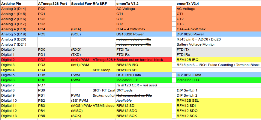
Note: The FTDI connector Tx and Rx pins are reversed on the PCB legend and on the Schematic. Data is received by the emonTx on the Tx pin and transmitted by the emonTx on the Rx pin.
Schematic and Board files
Proudly open source, the hardware designs are released under the Creative Commons Attribution-ShareAlike 3.0 Unported License:
emonTx Schematic and Board files:
https://github.com/openenergymonitor/emontx3/tree/master/hardware
CT Sensor Burden Resistor Calculations
The emonTx3 was primarily designed to use the YHDC SCT-013-000 100A, 2000 turns, current output CT sensors. Using this sensor:
CT channels 1-3 have a 22R burden resistor, and can measure up to 97A RMS (23.3kW @ 240V) using a YHDC SCT-013-00 CT which has 2000 turns.
CT channel 4 has a 120R burden and can measure up to 19.16 A RMS (4.6kW max @ 240 V)
These burden resistor values were choosen based on the following calculation:
Peak current primary = RMS current x sqrt(2)

Peak current secondary = Peak current primary / turns

Burden resistance = (Analog reference voltage x 0.5) / Peak current secondary
The analog reference voltage on the emonTx3 is 3.3V.
For a capability to measure 100A RMS primary current on CT channels 1-3, the calculated burden resistance is 23.3 Ohms. The closest resistor values are 22 Ohms and 24 Ohms. We selected 22 Ohms giving a measurement range of 0-97A RMS.
For a capability to measure 4kW or 16.7A RMS primary current on CT channels 4, the calculated burden resistance is 139.9 Ohms. The closest resistor values are 120 Ohms and 150 Ohms. We selected 120 Ohms giving a measurement range of 0-19.2A RMS or 4.6 kW @ 240V.
It is possible to change the standard burden resistors on an emonTx3 in order to change the measurement range when using the standard SCT-013-000 CT sensor. E.g to make all CT channels higher sensitivity 4.6kW channels. The burden resistor can also be changed to suit alternative CT sensors, in order to match the CT sensor output and desired measurement range with the emonTx3 ADC input voltage range.
The higher the burden resistance, the smaller the measurement range, the higher the low end accuracy will be. For higher accuracy it’s also worth choosing resistors with precise tolerance e.g ±0.1% or ±1%.
The following burden resistor value calculator is a useful tool to work out the best value: https://tyler.anairo.com/projects/open-energy-monitor-calculator
If the power level goes above the CT max rating, the voltage will go above 3.3V and the ATmega328’s ADC will be saturated. A 1K series resistor is used to limit input current to the ATmega. The ATmega 328’s internal clamping diodes will safely limit the voltage, preventing damage. http://openenergymonitor.org/emon/node/171
Alternative CT sensors
Using an SCT-016-000 with 6060 turns, at 200A max primary the recommended burden is 33R, which gives a max current rating of 214A
Using an SCT-006-000 with 533 turns, at 20A max primary the recommended burden is 30R, which gives a max current rating of 20.7A
Burden resistor power rating
From the YHDC SCT-013-000 test results, the maximum current in the secondary at saturation is 85 mA RMS (primary current 250A – 60kW! @ 240V).
CT 1-3: the max voltage across the 22 Ohm burden CT at saturation will be 1.87V (measured to be 1.5V RMS by @Robert.Wall). The power dissipation will be
1.87V x 85mA = 159 mW.CT 4: the max voltage across the 120 Ohm burden CT at saturation will be 10.2V (measured to be 5.2V RMS by @Robert.Wall). The power dissipation would be
10.2V x 85mA = 867mW.
However as the emonTx is designed for domestic use, the maximum rated fuse/RCB is 100A and therefore we can safely design for a maximum of 100A. The current in the secondary at 100A is 50mA (RMS).
Max voltage in CT 1-3 22R burden = 1.1Vrms (measured by Robert to be 0.935 Vrms).
Max power in 22R CT = 55mW.
Max voltage in CT 4 120R burden = 6V (measured by Robert to be 3.9 V rms)
Max power in 120R burden = 300mW
If a 0.25W resistor is used, the maximum current in the secondary would be 42mA. This equates to 82A or 19.7kW. CT4 is physically removed from CT1-3 and clearly marked as 4.6kW max.
Given testing results these values have been shown be to conservative, testing results are:
100 A, 22 R: Burden voltage = 0.935 Vrms, 2.612 V peak-peak, 40mW
100 A, 120 R: Burden voltage = 3.89 Vrms, 12.07 V peak-peak, 126mW
250 A, 22 R: Burden voltage = 1.498 Vrms, 5.626 V peak-peak, 102mW
250 A, 120 R: Burden voltage = 5.194 Vrms, 21.9 V peak-peak, 225mW
These are the maximum RMS voltages that can be developed.
Conclusion: 0.25W burden and 6V capacitor will be suitable ratings. A 0606 X5R 10uF 6.3V filtering capacitor can be used.
Power Supply Options
There are four ways to power the emonTx3:
USB to UART cable - only recommended for short periods while programming, it is recommended to remove all other power sources
5V DC Mini-USB cable - remove jumper JP2 when powering via DC if AC adapter is present
3 x AA Batteries - remove jumper JP2 when powering via DC if AC adapter is present
9V AC-AC power adapter - with jumper JP2 closed (If jumper 2 is left open then the AC-AC adapter will be used for power sampling but not to power the emonTx3 - see AC adapter voltage sensing and power supply below).
AC adapter voltage sensing and power supply.
The emonTx3 is designed to use an AC-AC adapter to provide an AC voltage sample and also depending on the configuration power as well. If the emonTx3 detects the presence of an AC adapter at startup, it will automatically implement Real Power and Vrms measurements by sampling the AC voltage. Real Power is what you get billed for, and depending on the appliances connected to the circuit being monitored, can vary significantly from Apparent Power - see Learn for more info on AC power theory. For best energy monitoring accuracy, we recommend powering the emonTx3 with an AC-AC adapter whenever possible.
Using the AC-AC adapter also enables the emonTx to monitor the direction of current flow. This is important for solar PV monitoring. If you notice a negative reading when you were expecting a positive one, reverse the orientation of the CT on the conductor.
Powering via the AC adapter is only suitable for standard CT monitoring and up to 4x DS18B20 temperature sensors, transmitting data via RFM69 433Mhz radio. The power supply circuit is only able to deliver a limited amount of current without impacting the voltage sensor accuracy.
To avoid damage to the emonTx3 circuits, the current drawn from the AC circuit should never exceed 60mA. If more than 10 mA of current is required, it is recommended to remove jumper 2 (JP2) and power the emonTx via the 5V mini-USB connector. When JP2 is removed, the AC-AC adapter (if connected) will be used only to provide an AC voltage sample, i.e. it will not power the emonTx.
If using the emonTx with an ESP8266 WiFi adapter a seperate 5V USB power supply is required.
Power supply design considerations
DC:
The emonTx3 has been designed to accept power via 5V USB, 3x AA batteries, UART connection or auxiliary input from terminal blocks.
In order to keep quiescent power loss to a minimum, a SOT32 MCP1700 LDO regulator was chosen for battery, USB 5V and FTDI power (5V) operation. The max input is 6V which is fine for battery (3 x AA) and USB operation. The MCP1700 has lower quiescent power consumption than the MCP1754 used in the AC-DC half-wave supply.
Powering from 5V USB (MCP1700 SOT22) Thermal Calculations
Max voltage drop required = 5.25-3.3=1.95V
Thermal resistance junction to ambient (JA) for MCP1700 SOT23A = 230 degrees C/W (from datashet)
Max case temperature = 150 degrees (from datasheet)
I max = (T case max – T ambient max)/thermal resistance (JA) / delta V max
I max (SOT23A) = ((150-40)/336)/1.95V = 168mA (for SOT23A)
The emonTx v3 does not support battery charging. Please ensure batteries are removed before connecting USB or FTDI power.
AC-DC:
For Power supply design circuit design, see blog posts: [1] ]2]
An SOT89 MCP1754 LDO regulator is used in the the AC-DC power supply circuit. The MCP17542 maximum input is 16 Volts. The larger SOT89 package is needed to dissipate the heat. The 47uF capacitor stores enough energy to see us through half wave cycles.
Thermal resistance junction to ambient (JA) for MCP1702 SOT-89 JA=153.3 degrees C/W (from datasheet P.22)
Max case temperature = 150 degrees (from datasheet)
Imax = (T case max – T ambient max)/thermal resistance (JA) / delta V max
At 12Vrms (max output of 9V AC-AC at max mains voltage)
ΔB = 12-3.3 = 10.7V
Imax (SOT-89) MCP1754 = ((150-40)/153.3)/10.7V = 67 mA (40C ambient)
worst case – max mains voltage and 50 degree ambient – max output = 61mA )
At V=10.4Vrms (output of 9V AC-AC at typical mains voltage)
ΔB = 10.4-3.3 = 7.1V
Imax (SOT-89) MCP1754 = ((150-40)/153.3)/7.1V = 101 mA (40C ambient)
At V=8.77Vrms (output of 9V AC-AC at min mains voltage)
ΔB = 8.77-3.3 = 3.62
Imax (SOT-89) MCP1754 = ((150-40)/153.3)/3.62V = 198 mA (40C ambient)
Using the MCP1754 with its higher thermal rating means the current limiting resistor dissapation rating is now the bottleneck to how much current can be drawn from the supply.
The AC-DC supply ripple is greatest at high current load and lowest mains voltage.
AD-DC Power Supply component ratings
Max operation output of circuit = 20mA
Maximum output of circuit = 30mA. The AC voltage sample will be affected and the MCP1702 could overheat if ambient temperature is 40-50 degrees. 30mA should be drawn only for short periods. E.g. SRF radio Transmitting.
Do not try to draw more than 30mA. This will result in the 3.3V rail dropping significantly, and excess current passing through the 56R current limiting resistor. This will cause the resistor to overheat.
Halfwave rectifier diode D1: Worst case at highest mains voltage and extreme current output: 30mW average
Current limiting resistor: 56R R29. At worst case, lowest mains voltage and extreme current output: Average power dissipation: 222mW. 0.25W resistor will be ok.
Reservoir capacitor C18 47uF: should not see a higher voltage than 12V since the zener diode will clamp the voltage to 12V. A capacitor rating of 16V will be more than enough.
De-coupling 1uF capacitor C17 voltage rating: The transformer is ground referenced, the other side referenced to 1.65 V – so 6.3 V should be plenty. The alternating component of the voltage should be very small, else we have phase shift problems. [The major part of the 12V will appear across the divider chain, R13 + R14.]
Zener diode - 12V MCP1702 over voltage protection 106mW average - not needed since MCP1754 is used and can handle 16V input
Update V3.4.5: Swap to LDK320ADU33R with a max input voltage of 18V since at highest mains voltage 16V max input of MCP1754 was being exceeded**
Enclosure
The emonTx V3 PCB is 100mm x 80mm and enclosed in an EBS80 enclosure sourced from Lincoln Binns, see data sheet.
Community contributed