6 CT Expansion board
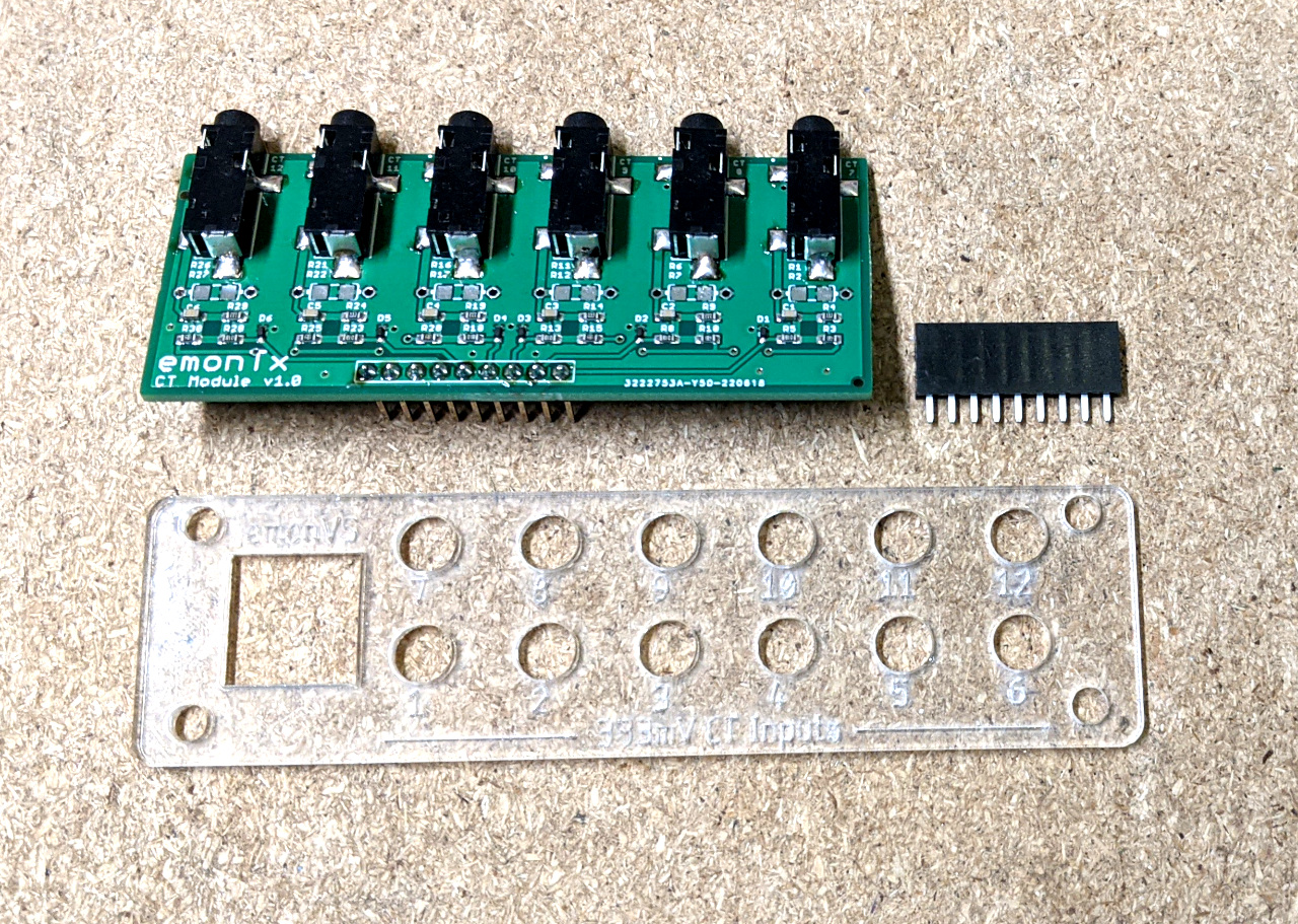
The 6 CT Expansion board adds a further 6x CT inputs to the EmonTx4, giving a total of 12 CT inputs. This can be used with example firmware that is provided as part of the new EmonLibDB library, supporting both single phase and 3 phase monitoring.
Note: Firmware configuration, compilation and upload required using the Arduino IDE, see firmware guide below for details.
Installation guide
Upgrading: If ordered separately to the EmonTx4 the expansion board comes with a 12 CT fascia to replace the standard 6 CT version. A 9-way header is also included that needs to be soldered in place on the EmonTx4.
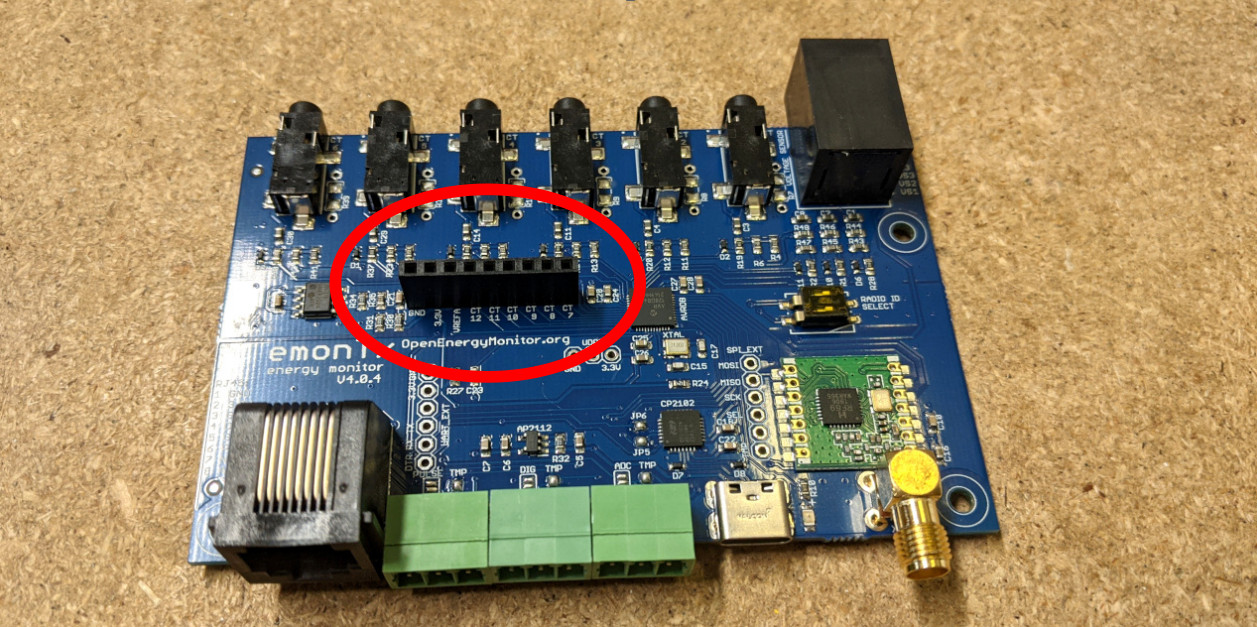
Place the 9 way header on the top side of the board as circled below:
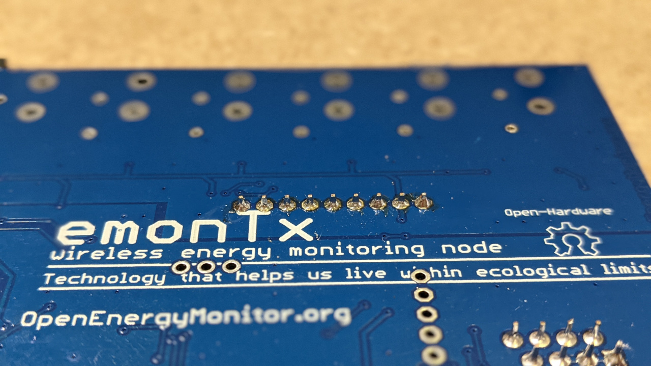
Solder the pins on the bottom side, taking care not to bridge across the pins:
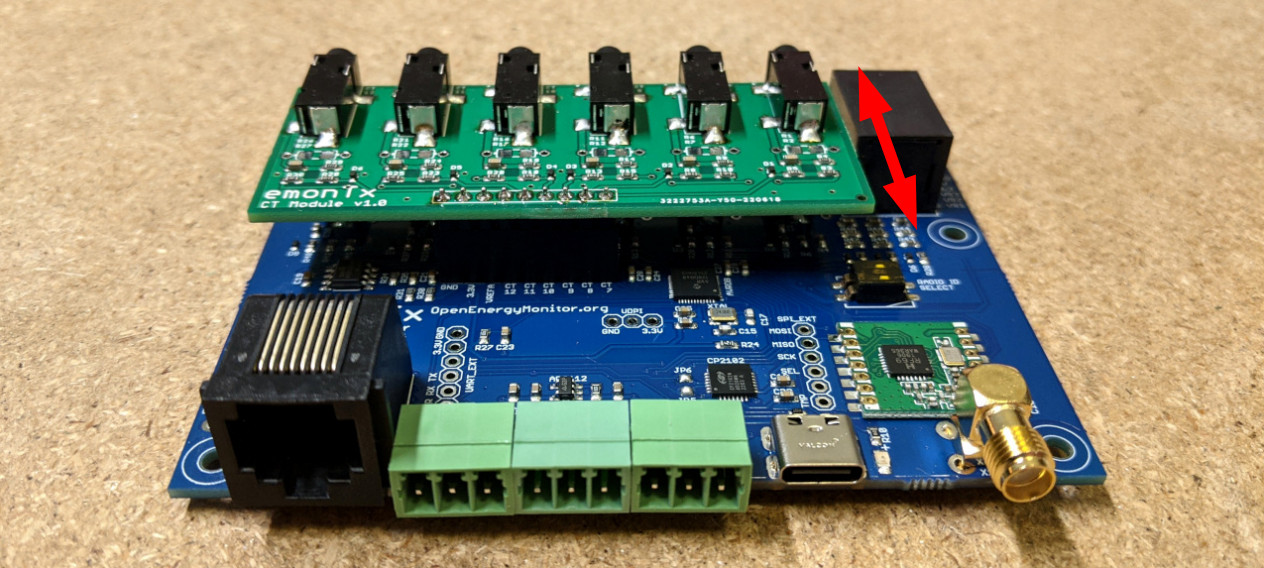
Note: The mechanical attachment of the expansion board is not very secure. It relies on the 9 way PCB header connection. Care needs to be taken when plugging in expansion board CTs as the board can flex on the header. This is something we plan to improve on future versions.
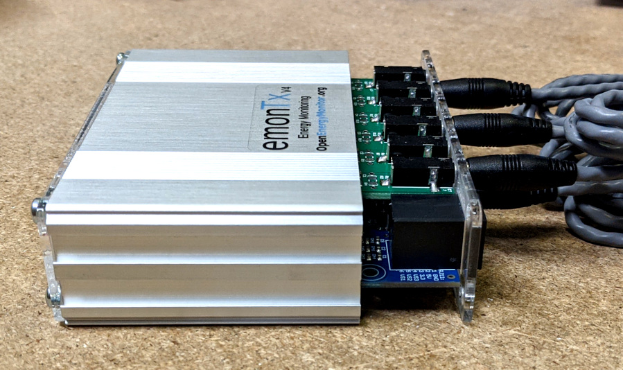
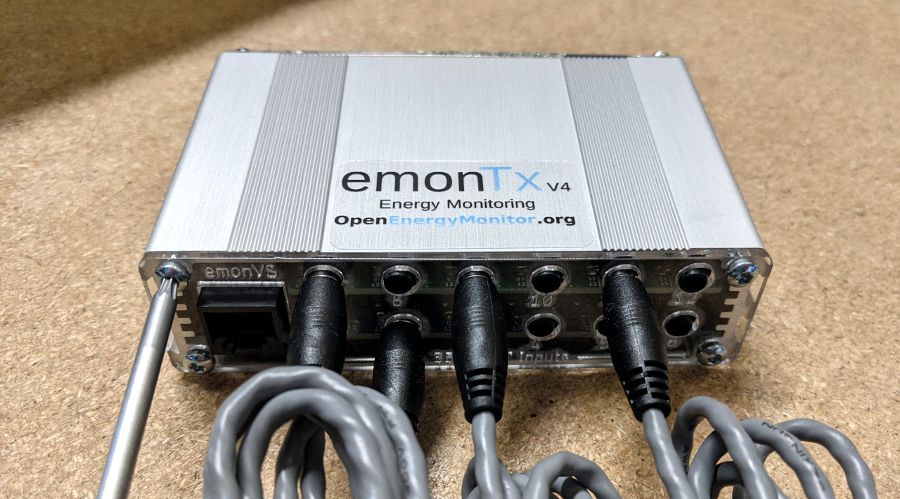
We recommend connecting the CT sensors through the face plate, outside of the aluminium enclosure first and then attaching the face plate to the enclosure second. This ensures that the CT’s are all fully inserted and that the pressure on the header is minimised. See pictures below.
Slide the emonTx4 board, expansion board, face plate and CT jacks into the case:
Screw in the torx screws (torx size T10):
Firmware guide
If you are using the newer “LowPowerLabs” radio firmware, you will be able to flash precompiled firmware. See the firmware guide to determine which firmware you require for your needs.
If you are using the older “JeeLib Classic” radio firmware (pre 2022 monitoring installations), using the 6 CT channel expansion board may require compiling and uploading custom configuration of the emonTx4 firmware. Start by setting up the Arduino IDE environment following the firmware guide.
Open the base firmware emon_DB_12CT from the avrdb_firmware firmware repository.
1. Make sure to select emonTx4 as the hardware variant:
// 1. Set hardware variant
// Options: EMONTX4, EMONTX5, EMONPI2
#define EMONTX4
2. Set NUM_V_CHANNELS to 1 for single phase or 3 for three phase:
// 3. Set number of voltage channels (1 for single phase, 3 for three phase)
#define NUM_V_CHANNELS 3
3. Adjust voltage and CT sensor calibration as required (lines 187-207):
Voltage inputs: 101.3 here refers to 101.3% of the default calibration value. Please see emonLibDB user guide for more info as well. 0.16 refers to the voltage sensor phase calibration.
  EmonLibDB_set_vInput(1, 101.3, 0.16);
#if NUM_V_CHANNELS == 3
  EmonLibDB_set_vInput(2, 101.3, 0.16);
  EmonLibDB_set_vInput(3, 101.3, 0.16);
#endif
Current channel inputs: 100.0 here refers to 100A CT sensors. If you have 20A or 50A CT sensors change the relevant channels to 20.0 or 50.0 to match the CT sensor. 3.2 refers to the CT sensor phase calibration.
  EmonLibDB_set_cInput(1, 20.0, 3.2);
  EmonLibDB_set_cInput(2, 20.0, 3.2);
  EmonLibDB_set_cInput(3, 20.0, 3.2);
  EmonLibDB_set_cInput(4, 20.0, 3.2);
  EmonLibDB_set_cInput(5, 20.0, 3.2);
  EmonLibDB_set_cInput(6, 20.0, 3.2);

#ifdef EXPANSION_BOARD
  EmonLibDB_set_cInput(7, 20.0, 3.2);
  EmonLibDB_set_cInput(8, 20.0, 3.2);
  EmonLibDB_set_cInput(9, 20.0, 3.2);
  EmonLibDB_set_cInput(10, 20.0, 3.2);
  EmonLibDB_set_cInput(11, 20.0, 3.2);
  EmonLibDB_set_cInput(12, 20.0, 3.2);
#endif
4. Link voltage and current sensors to define the power & energy measurements. The firmware includes default configuration for the selected NUM_V_CHANNELS (1 phase or 3 phase). In the single phase example all CT sensors are connected to voltage phase 1. In the three phase code, the allocation is CT1 = phase1, CT2 = phase2, CT3 = phase3 etc.
#if NUM_V_CHANNELS == 1
  EmonLibDB_set_pInput(1, 1);                  // CT1, V1 (etc)
  EmonLibDB_set_pInput(2, 1);
  EmonLibDB_set_pInput(3, 1);
  EmonLibDB_set_pInput(4, 1);
  EmonLibDB_set_pInput(5, 1);
  EmonLibDB_set_pInput(6, 1);
#ifdef EXPANSION_BOARD
  EmonLibDB_set_pInput(7, 1);                  // CT7, V1 (etc)
  EmonLibDB_set_pInput(8, 1);
  EmonLibDB_set_pInput(9, 1);
  EmonLibDB_set_pInput(10, 1);
  EmonLibDB_set_pInput(11, 1);
  EmonLibDB_set_pInput(12, 1);
#endif
#endif

#if NUM_V_CHANNELS == 3
  EmonLibDB_set_pInput(1, 1);                  // CT1, V1 (etc)
  EmonLibDB_set_pInput(2, 2);
  EmonLibDB_set_pInput(3, 3);
  EmonLibDB_set_pInput(4, 1);
  EmonLibDB_set_pInput(5, 2);
  EmonLibDB_set_pInput(6, 3);
#ifdef EXPANSION_BOARD
  EmonLibDB_set_pInput(7, 1);                  // CT7, V1 (etc)
  EmonLibDB_set_pInput(8, 2);
  EmonLibDB_set_pInput(9, 3);
  EmonLibDB_set_pInput(10, 1);
  EmonLibDB_set_pInput(11, 2);
  EmonLibDB_set_pInput(12, 3);
#endif
#endif
Note: It is also possible to measure Line-Line loads, see Line-Line loads: example lines 253-267.
5. Compile and upload your configured firmware to the EmonTx4. Note compilation and upload settings as covered in the EmonTx4 How to compile and upload firmware guide.
6. To receive the radio packet data on an emonPi or emonBase first make sure that you are running LowPowerLabs radio firmware on the emonPi or emonBase receiver.
If you have existing nodes running the original JeeLib classic radio format, the firmware on these will also need to be updated if everything is to continue talking to each other.
If you have an emonPi make sure that it’s running the latest emonPi LowPowerLabs firmware, this can be uploaded from the local emoncms Admin > Update page.
If you bought an emonBase alongside an emonTx4 and selected the standard radio format option the radio configuration should already be correct and ready to receive data from the EmonTx4 running the above firmware example.
7. Configure emonHub to decode the emon_DB_12CT radio packet.
If you have the latest version of emonhub with autoconf enabled, it will automatically populate the node decoder configuration below. If you have an older system with autoconf disabled, follow the following manual steps:
On your local emonPi/emonBase navigate to Setup > Emonhub > Edit Config.
If you already have a node configuration in the [nodes] section for the EmonTx4 under the same nodeid as above, remove this first.
Add the following node decoder in its place (Adjust the nodeid to match the configured nodeid as set in the firmware above):
[[28]]
    nodename = emonTx4_28
    [[[rx]]]
        names = MSG, Vrms1, Vrms2, Vrms3, P1, P2, P3, P4, P5, P6, E1, E2, E3, E4, E5, E6, pulse, Analog
        datacodes = L, h, h, h, h, h, h, h, h, h, l, l, l, l, l, l, L, H
        scales = 1.0, 0.01, 0.01, 0.01, 1.0, 1.0, 1.0, 1.0, 1.0, 1.0, 1.0, 1.0, 1.0, 1.0, 1.0, 1.0, 1.0, 1.0
        units = n, V, V, V, W, W, W, W, W, W, Wh, Wh, Wh, Wh, Wh, Wh, p, n

[[29]]
    nodename = emonTx4_29
    [[[rx]]]
        names = MSG, Vrms2, Vrms3, P7, P8, P9, P10, P11, P12, E7, E8, E9, E10, E11, E12, digPulse, anaPulse
        datacodes = L, h, h, h, h, h, h, h, h, l, l, l, l, l, l, L, L
        scales = 1.0, 0.01, 0.01, 1.0, 1.0, 1.0, 1.0, 1.0, 1.0, 1.0, 1.0, 1.0, 1.0, 1.0, 1.0, 1.0, 1.0
        units = n, V, V, W, W, W, W, W, W, Wh, Wh, Wh, Wh, Wh, Wh, p, p
8. That should be it! you should now see the EmonTx4 data appear both in the EmonHub log window and as inputs on the Emoncms inputs page :tada:
For more information, please see forum thread: EmonTx4 3-phase support with emonLibDB